Aliasing PPGTT [part 2]
Table Of Contents
Overview
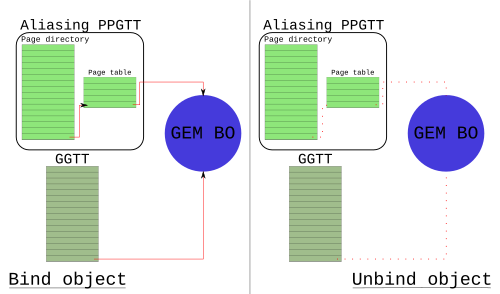
Pictures are the right way to start.

There is exactly one thing to get from the above drawing, everything else is just to make it as close to fact as possible.
- The aliasing PPGTT (aliases|shadows|mimics) the global GTT.
The wordy overview
Support for Per-process Graphics Translation Tables (PPGTT) debuted on Sandybridge (GEN6). The features provided by hardware are a superset of Aliasing PPGTT, which is entirely a software construct. The most obvious unimplemented feature is that the hardware supports multiple PPGTTs. Aliasing PPGTT is a single instance of a PPGTT. Although not entirely true, it's easiest to think of the Aliasing PPGTT as a set page table of page tables that is maintained to have the identical mappings as the global GTT (the picture above). There is more on this in the summary section
Until recently, aliasing PPGTT was the only way to make use of the hardware feature (unless you accidentally stepped into one of my personal branches). Aliasing PPGTT is implemented as a performance feature (more on this later). It was an important enabling step for us as well as it provided a good foundation for the lower levels of the real PPGTT code.
In the following, I will be using the HSW PRMs as a reference. I'll also assume you've read, or understand part 1
Selecting GGTT or PPGTT
Choosing between the GGTT and the Aliasing PPGTT is very straight forward. The choice is provided in several GPU commands. If there is no explicit choice, than there is some implicit behavior which is usually sensible. The most obvious command to be provided with a choice is MI_BATCH_BUFFER_START. When a batchbuffer is submitted, the driver sets a single bit that determines whether the batch will execute out of the GGTT or a Aliasing PPGTT (Actually it will use whatever the current PPGTT is, but for this post, that is always the Aliasing PPGTT). Several commands as well, like PIPE_CONTROL, have a bit to direct which to use for the reads or writes that the GPU command will perform.
Architecture
The names for all the page table data structures in hardware are the same as for
IA CPU. You can see the Intel® 64 and IA-32 Architectures Software Developer
Manuals
for more information. (At the time of this post: page 1988 Vol3. 4.2
HIERARCHICAL PAGING STRUCTURES: AN
OVERVIEW).
I don't want to rehash the HSW PRMs too much, and I am probably not allowed
to won't copy the diagrams. However, for the sake of having a consolidated
post, I will rehash the most pertinent parts.
There is one conceptual Page Directory for a PPGTT - the docs call this a set of Page Directory Entries (PDEs), however since they are contiguous, calling it a Page Directory makes a lot of sense to me. In fact, going back to the Ironlake docs, that seems to be the case. So there is one page directory with up to 512 entries, each pointing to a page table. There are several good diagrams which I won't bother redrawing in the PRMs (Page walk, Two-Level Per-Process Virtual Memory)
| 31:12 | 11:04 | 03:02 | 01 | 0 |
|---|---|---|---|---|
| Physical Page Address 31:12 | Physical Page Address 39:32 | Rsvd | Page size (4K/32K) | Valid |
| 31:12 | 11 | 10:04 | 03:01 | 0 |
|---|---|---|---|---|
| Physical Page Address 31:12 | Cacheability Control[3] | Physical Page Address 38:32 | Cacheability Control[2:0] | Valid |
There's some things we can get from this for those too lazy to click on the links to the docs.
- PPGTT page tables exist in physical memory.
- PPGTT PTEs have the exact same layout as GGTT PTEs.
- PDEs don't have cache attributes (more on this later).
- There exists support for big pages ((Big pages have the same goal as they do on the CPU - to reduce TLB pressure. To date, there has been no implementation of big pages for GEN (though a while ago I started putting something together). There has been some anecdotal evidence that there isn't a big win to be had for many workloads we care about, and so this remains a low priority.))
With the above definitions, we now can derive a lot of interesting attributes about our GPU. As already stated, the PPGTT is a two-level page table (I've not yet defined the size).
- A PDE is 4 bytes wide
- A PTE is 4 bytes wide
- A Page table occupies 4k of memory.
- There are 4k/4 entries in a page table.
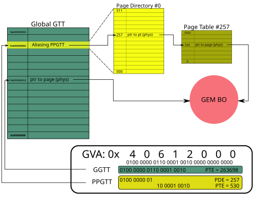
With all this information, I now present you a slightly more accurate picture.

Size
PP_DCLV - PPGTT Directory Cacheline Valid Register: As the spec tells us, "This register controls update of the on-chip PPGTT Directory Cache during a context restore." This statement is directly contradicted in the very next paragraph, but the important part is the bit about the on-chip cache. This register also determines the amount of virtual address space covered by the PPGTT. The documentation for this register is pretty terrible, so a table is actually useful in this case.
PPGTT Directory Cacheline Valid Register (from the docs)
| 63:32 | 31:0 |
|---|---|
| MBZ | PPGTT Directory Cache Restore [1..32] 16 entries |
DCLV, the right way
| 31 | 30 | ... | 1 | 0 |
|---|---|---|---|---|
| PDE[511:496] enable | PDE [495:480] enable | ... | PDE[31:16] enable | PDE[15:0] enable |
The, "why" is not important. Each bit represents a cacheline of PDEs, which is how the register gets its name ((This register thus allows us to limit, or make a sparse address space for the PPGTT. This mechanism is not used, even in the full PPGTT patches)). A PDE is 4 bytes, there are 64b in a cacheline, so 64/4 = 16 entries per bit. We now know how much address space we have.
512 PDEs 1024 PTEs per PT 4096 PAGE_SIZE = 2GB
Location
PP_DIR_BASE: Sadly, I cannot find the definition to this in the public HSW docs. However, I did manage to find a definition in the Ironlake docs yay me. There are several mentions in more recent docs, and it works the same way as is outlined on Ironlake. Quoting the docs again, "This register contains the offset into the GGTT where the (current context’s) PPGTT page directory begins." We learn a very important caveat about the PPGTT here - the PPGTT PDEs reside within the GGTT.
Programming
With these two things, we now have the ability to program the location, and size (and get the thing to load into the on-chip cache). Here is current i915 code which switches the address space (with simple comments added). It's actually pretty ho-hum.
...
ret = intel_ring_begin(ring, 6);
if (ret)
    return ret;

intel_ring_emit(ring, MI_LOAD_REGISTER_IMM(2));
intel_ring_emit(ring, RING_PP_DIR_DCLV(ring));
intel_ring_emit(ring, PP_DIR_DCLV_2G);       // program size
intel_ring_emit(ring, RING_PP_DIR_BASE(ring));
intel_ring_emit(ring, get_pd_offset(ppgtt)); // program location
intel_ring_emit(ring, MI_NOOP);
intel_ring_advance(ring);
...
As you can see, we program the size to always be the full amount (in fact, I fixed this a long time ago, but never merged). Historically, the offset was at the top of the GGTT, but with my PPGTT series merged, that is abstracted out, and the simple get_pd_offset() macro gets the offset within the GGTT. The intel_ring_emit() stuff is because the docs recommended setting the registers via the GPU's LOAD_REGISTER_IMMEDIATE command, though empirically it seems to be fine if we simply write the registers via MMIO (for Aliasing PPGTT). See my previous blog post if you want more info about the commands execution in the GPU's ringbuffer. If it's easier just pretend it's 2 MMIO writes.
Initialization
All of the resources are allocated and initialized upfront. There are 3 main steps. Note that the following comes from a relatively new kernel, and I have already submitted patches which change some of the cosmetics. However, the concepts haven't changed for pre-gen8.
1. Allocate space in the GGTT for the PPGTT PDEs
ret = drm_mm_insert_node_in_range_generic(&dev_priv->gtt.base.mm,
                      &ppgtt->node, GEN6_PD_SIZE,
                      GEN6_PD_ALIGN, 0,
                      0, dev_priv->gtt.base.total,
                      DRM_MM_TOPDOWN);
2. Allocate the page tables
for (i = 0; i < ppgtt->num_pd_entries; i++) {
    ppgtt->pt_pages[i] = alloc_page(GFP_KERNEL);
    if (!ppgtt->pt_pages[i]) {
        gen6_ppgtt_free(ppgtt);
        return -ENOMEM;
    }
}
3. [possibly] IOMMU map the pages
for (i = 0; i < ppgtt->num_pd_entries; i++) {
    dma_addr_t pt_addr;

pt_addr = pci_map_page(dev->pdev, ppgtt->pt_pages[i], 0, 4096,
               PCI_DMA_BIDIRECTIONAL);
...
As the system binds, and unbinds objects into the aliasing PPGTT, it simply writes the PTEs for the given object (possibly spanning multiple page tables). The PDEs do not change. PDEs are mapped to a scratch page when not used, as are the PTEs.
IOMMU
As we saw in step 3 above, I mention that the page tables may be mapped by the IOMMU. This is one important caveat that I didn't fully understand early on, so I wanted to recap a bit. Recall that the GGTT is allocated out of system memory during the boot firmware's initialization. This means that as long as Linux treats that memory as special, everything will just work (just don't look for IOMMU implicated bugs on our bugzilla). The page tables however are special because they get allocated after Linux is already running, and the IOMMU is potentially managing the memory. In other words, we don't want to write the physical address to the PDEs, we want to write the dma address. Deferring to wikipedia again for the description of an IOMMU., that's all.It tripped be up the first time I saw it because I hadn't dealt with this kind of thing before. Our PTEs have worked the same way for a very long time when mapping the BOs, but those have somewhat hidden details because they use the scatter-gather functions.
Feel free to ask questions in the comments if you need more clarity - I'd probably need another diagram to accommodate.
Cached page tables
Let me be clear, I favored writing a separate post for the Aliasing PPGTT because it gets a lot of the details out of the way for the post about Full PPGTT. However, the entire point of this feature is to get a [to date, unmeasured] performance win. Let me explain... Notice bits 4:3 of the ECOCHK register. Similarly in the i915 code:
ecochk = I915_READ(GAM_ECOCHK);
if (IS_HASWELL(dev)) {
    ecochk |= ECOCHK_PPGTT_WB_HSW;
} else {
    ecochk |= ECOCHK_PPGTT_LLC_IVB;
    ecochk &= ~ECOCHK_PPGTT_GFDT_IVB;
}
I915_WRITE(GAM_ECOCHK, ecochk);
What these bits do is tell the GPU whether (and how) to cache the PPGTT page tables. Following the Haswell case, the code is saying to map the PPGTT page table with write-back#Writing_policies) caching policy. Since the writes for Aliasing PPGTT are only done at initialization, the policy is really not that important.
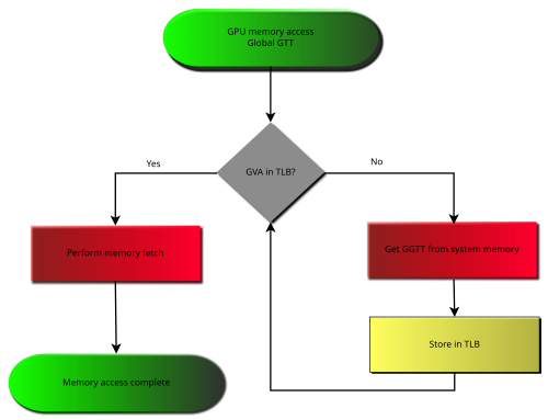
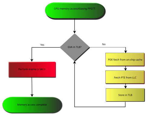
Below is how I've chosen to distinguish the two. I have no evidence that this is actually what happens, but it seems about right.


Red means slow. The point which was hopefully made clear above is that when you miss the TLB on a GGTT access, you need to fetch the entry from memory, which has a relatively high latency. When you miss the TLB on a PPGTT access, you have two caches (the special PDE cache for PPGTT, and LLC) which are backing the request. Note there is an intentional bug in the second diagram - you may miss the LLC on the PTE fetch also. I was trying to keep things simple, and show the hopeful case.
[Because of this, all mappings which do not require GGTT mappings get mapped to the aliasing PPGTT.]
Distinctions from the GGTT
At this point I hope you're asking why we need the global GTT at all. There are a few limited cases where the hardware is incapable (or it is undesirable) of using a per process address space.
A brief description of why, with all the current callers of the global pin interface.
- Display: Display actually implements it's own version of the GGTT. Maintaining
the logic to support multiple level page tables was both costly, and
unnecessary. Anything relating to a buffer being scanned out to the display
must always be mapped into the GGTT. Ie xpect this to be true, forever.
- i915_gem_object_pin_to_display_plane(): page flipping
- intel_setup_overlay(): overlays
- Ringbuffer: Keep in mind that the aliasing PPGTT is a special case of PPGTT.
The ringbuffer must remain address space and context agnostic. It doesn't make
any sense to connect it to the PPGTT, and therefore the logic does not support
it. The ringbuffer provides direct communication to the hardware's execution
logic - which would be a nightmare to synchronize if we forget about the
security nightmare. If you go off and think about how you would have a
ringbuffer mapped by multiple address spaces, you will end up with something
like
execlists.
- allocate_ring_buffer()
- HW Contexts Extremely similar to ringbuffer.
- intel_alloc_context_page(): Ironlake RC6
- i915_gem_create_context(): Create the default HW context
- i915_gem_context_reset(): Re-pin the default HW context
- do_switch(): Pin the logical context we're switching to
- Hardware status page: The use of this, prior to execlists, is much like
rinbuffers, and contexts. There is a per process status page with execlists.
- init_status_page()
- Workarounds:
- init_pipe_control(): Initialize scratch space for workarounds.
- intel_init_render_ring_buffer(): An i830 w/a I won't bother to understand
- render_state_alloc(): Full initialization of GPUs 3d state from within the kernel
- Other
- i915_gem_gtt_pwrite_fast(): Handle pwrites through the aperture. More info The Global GTT [Part 1].
- i915_gem_fault(): Map an object into the aperture for gtt_mmap. More info The Global GTT [Part 1].
- i915_gem_pin_ioctl(): The DRI1 pin interface.
GEN8 disambiguation
Off the top of my head, the list of some of the changes on GEN8 which will
get more detail in a later post. These changes are all upstream from the
original Broadwell integration.
- PTE size increased to 8b
- Therefore, 512 entries per table
- Format mimics the CPU PTEs
- PDEs increased to 8b (remains 512 PDEs per PD)
- Page Directories live in system memory
- GGTT no longer holds the PDEs.
- There are 4 PDPs, and therefore 4 PDs
- PDEs are cached in LLC instead of special cache (I'm guessing)
- Page Directories live in system memory
- New HW PDP (Page Directory Pointer) registers point to the PDs, for legacy 32b
addressing.
- PP_DIR_BASE, and PP_DCLV are removed
- Support for 4 level page tables, up to 48b virtual address space.
- PML4[PML4E]->PDP
- PDP[PDPE] -> PD
- PD[PDE] -> PT
- PT[PTE] -> Memory
- Big pages are now 64k instead of 32k (still not implemented)
- New caching interface via PAT like structure
Summary
There's actually an interesting thing that you start to notice after reading Distinctions from the GGTT. Just about every thing mapped into the GGTT shouldn't be mapped into the PPGTT. We already stated that we try to map everything else into the PPGTT. The set of objects mapped in the GGTT, and the set of objects mapped into the PPGTT are disjoint (There actually is a case on GEN6 which requires both. Currently this need is implemented by drivers/gpu/drm/i915/i915_gem_execbuffer.c: i915_gem_execbuffer_relocate_entry()). The patches to make this work are not yet merged. I'd put an image here to demonstrate, but I am feeling lazy and I really want to get this post out today.
Recapping:
- The Aliasing PPGTT is a single instance of the hardware feature: PPGTT.
- Aliasing PPGTT was designed as a drop in performance replacement to the GGTT.
- GEN8 changed a lot of architectural stuff.
- The Aliasing PPGTT shouldn't actually alias the GGTT because the objects they map are a disjoint set.