Framebuffer Modifiers Part 1
Table Of Contents
Introduction
In a now pretty well established tradition on my part, I am posting on things I no longer work on!
I gave a talk on modifiers at XDC 2017 and Linux Plumbers 2017 audio only. It was always my goal to have a blog post accompany the work. Relatively shortly after the talks, I ended up leaving graphics and so it dropped on the priority list.
I'm splitting this up into two posts. This post will go over the problem, and solutions. The next post will go over the implementation details.
Modifiers
Each 3d computational unit in an Intel GPU is called an Execution Unit (EU). Aside from what you might expect them to do, like execute shaders, they may be used for copy operations (itself a shader), or compute operations (also, shaders). All of these things require memory bandwidth in order to complete their task in a timely manner.
Modifiers were the chosen solution in order to allow end to end renderbuffer [de]compression to work, which is itself designed to reduce memory bandwidth needs in the GPU and display pipeline. End to end renderbuffer compression simply means that through all parts of the GPU and display pipeline, assets are read and written to in a compression scheme that is capable of reducing bandwidth (more on this later).
Modifiers are relatively simple concept. They are modifications that are applied to a buffer's layout. Typically a buffer has a few properties, width, height, and pixel format to name a few. Modifiers can be thought of as ancillary information that is passed along with the pixel data. It will impact how the data is processed or displayed. One such example might be to support tiling, which is a mechanism to change how pixels are stored (not sequentially) in order for operations to make better use of locality for caching and other similar reasons. Modifiers were primarily designed to help negotiate modified buffers between the GPU rendering engine and the display engine (usually by way of the compositor). In addition, other uses can crop up such as the video decode/encode engines.
A Waste of Time and Gates
My understanding is that even now, 3 years later, full modifier support isn't readily available across all corners of the graphics ecosystem. Many hardware features are being entirely unrealized. Upstreaming sweeping graphics features like this one can be very time consuming and I seriously would advise hardware designers to take that into consideration (or better yet, ask your local driver maintainer) before they spend the gates. If you can make changes that don't require software, just do it. If you need software involvement, the longer you wait, the worse it will be.
They weren't new even when I made the presentation 3.5 years ago.
commit e3eb3250d84ef97b766312345774367b6a310db8
Author: Rob Clark <robdclark@gmail.com>
Date:   6 years ago

    drm: add support for tiled/compressed/etc modifier in addfb2
I managed to land some stuff:
commit db1689aa61bd1efb5ce9b896e7aa860a85b7f1b6
Author: Ben Widawsky <ben@bwidawsk.net>
Date:   3 years, 7 months ago

    drm: Create a format/modifier blob
Admiring the Problem
Back of the envelope requirement for a midrange Skylake GPU from the time can be calculated relatively easily. 4 years ago, at the frequencies we run our GPUs and their ISA, we can expect roughly 1GB⁄s for each of the 24 EUs.
A 4k display:
3840px × 2160rows × 4Bpp × 60HZ = 1.85GB⁄s
24GB⁄s + 1.85GB⁄s = 25.85GB⁄s
This by itself will oversaturate single channel DDR4 bandwidth (which was what was around at the time) at the fastest possible clock. As it turns out, it gets even worse with compositing. Most laptops sporting a SKL of this range wouldn't have a 4k display, but you get the idea.
The picture (click for larger SVG) is a typical "flow" for a composited desktop using direct rendering with X or a Wayland compositor using EGL. In this case, drawing a Rubik's cube looking thing into a black window.

Using this simple Rubik's cube example I'll explain each of the steps so that we can understand where our bandwidth is going and how we might mitigate that. This is just the overview, so feel free to move on to the next section. Since the example will be trivial, and the window is small (and only a singleton) it won't saturate the bandwidth, but it will demonstrate where the bandwidth is being consumed, and open up a discussion on how savings can be achieved.
Rendering and Texturing
For the example, no processing happens other than texturing. In a simple world, the processing of the shader instructions doesn't increase the memory bandwidth cost. As such, we'll omit that from the details.
The main steps on how you get this Rubik's cube displayed are
- upload a static texture
- read from static texture
- write to offscreen buffer
- copy to output frame
- scanout from output
More details below...
Texture Upload
Getting the texture from the application, usually from disk, into main memory, is what I'm referring to as texture upload. In terms of memory bandwidth, you are using write bandwidth to write into the memory.

Textures may either be generated by the 3d application, which would be trivial for this example, or they may be authored using a set of offline tools and baked into the application. For any consequential use, the latter is predominantly used. Certain surface types are often dynamically generated though, for example, the shadow mapping technique will generate depth maps. Those dynamically generated surfaces actually will benefit even more (more later).
This is pseudo code (but close to real) to upload the texture in OpenGL:
const unsigned height = 128;
const unsigned width = 64;
const void *data = ... // rubik's cube
GLuint tex;

glGenTextures(1, &tex);
glBindTexture(GL_TEXTURE_2D, texture);
glTexImage2D(GL_TEXTURE_2D, 0, GL_RGB, width, height, 0, GL_RGB, GL_UNSIGNED_BYTE, data);
glGenerateMipmap(GL_TEXTURE_2D);
I'm going to punt on explaining mipmaps, which are themselves a mechanism to conserve memory bandwidth. If you have no understanding, I'd recommend reading up on mipmaps. This wikipedia article looks decent to me.
Texture Sampling
Once the texture is bound, the graphics runtime can execute shaders which can
reference those textures. When the shader requests a color value (also known as
sampling) from the texture, it's possiblelikely that the calculated
coordinate within the texture will be in between pixels. The hardware will have
to return a single color value for the sample point and the way it interpolates
is chosen by the graphics runtime. This is referred to as a filter
 |
|---|
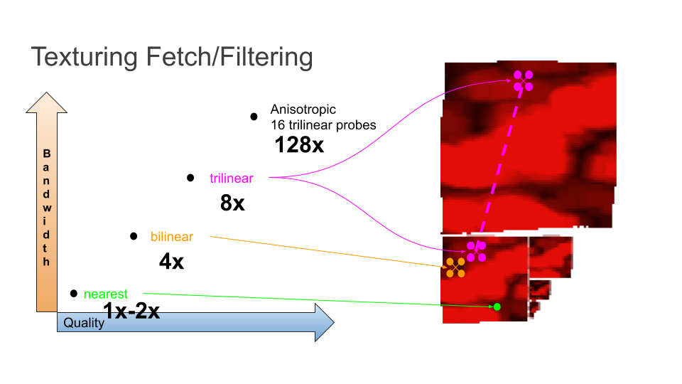
| Texture Fetch/Filtering |
- Nearest: Take the value of the closest two pixels and interpolate. If the texture coordinate hits a single pixel, don't interpolate.
- Bilinear: Take the surround 4 pixels and interpolate based on distance for the texture coordinate
- Trilinear: Bilinear, but also interpolate between the two closest mipmaps. (I skipped discussing mipmaps, but part of the texture fetch involves finding the nearest miplevel.
- Anisotropic: It's complicated. Let's say 16x trilinear.
Here's the GLSL to fetch the texture:
#version 330

uniform sampler2D tex;
in vec2 texCoord;
out vec4 fragColor;

void main() {
    vec4 temp = texelFetch(tex, ivec2(texCoord));
    fragColor = temp;
}
The above actually does something that's perhaps not immediately obvious. fragColor = temp;. This actually instructs the fragment shader to write out that value to a surface which is bound for output (usually a framebuffer). In other words, there are two steps here, read and filter a value from the texture, write it back out.
The part of the overall diagram that represents this step:

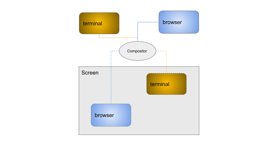
Composition
In the old days of X, and even still when not using the composite extension, the graphics applications could be given a window to write the pixels directly into the resulting output. The X window manager would mediate resize and move events, letting the client update as needed. This has a lot of downsides which I'll say are out of scope here. There is one upside that is in scope though, there's no extra copy needed to create the screen composition. It just is what it is, tearing and all.
If you don't know if you're currently using a compositor, you almost certainly are using one. Wayland only composites, and the number of X window managers that don't composite is very few. So what exactly is compositing? Simply put it's a window manager that marshals frame updates from clients and is responsible for drawing them on the final output. Often the compositor may add its own effects such as the infamous wobbly windows. Those effects themselves may use up bandwidth!
 |
|---|
| Simplified compositor block diagram |
Applications will write their output into what's referred to as an offscreen buffer. 👋👋 The compositor will read the output and copy it into what will become the next frame. What this means from a bandwidth consumption perspective is that the compositor will need to use both read and write bandwidth just to build the final frame. 👋👋
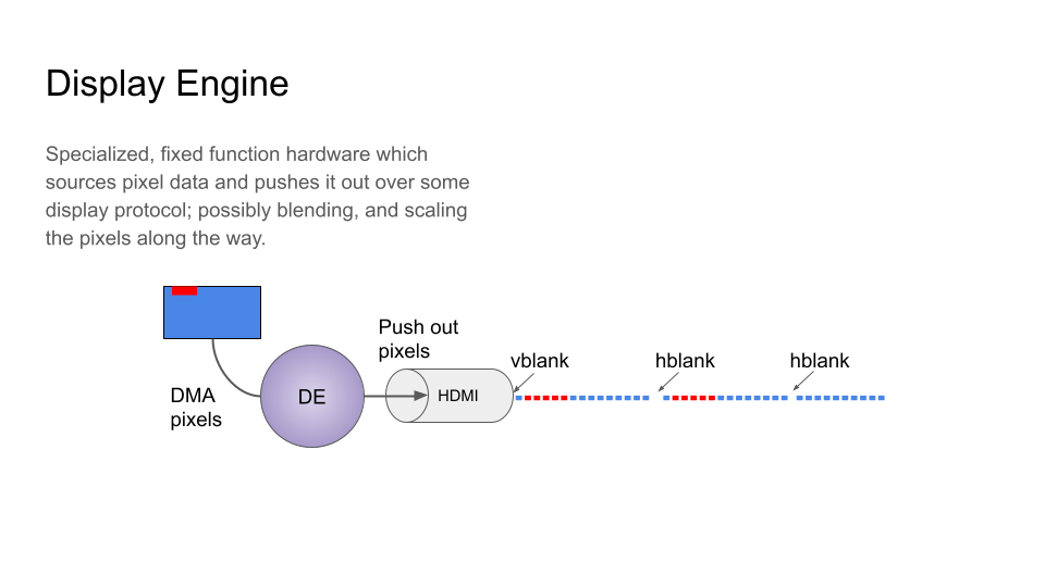
Display
It's the mundane part of this whole thing. Pixels are fetched from memory and pushed out onto whatever display protocol.
 |
|---|
| Display Engine |
Perhaps the interesting thing about the display engine is it has fairly isochronous timing requirements and can't tolerate latency very well. As such, it will likely have a dedicated port into memory that bypasses arbitration with other agents in the system that are generating memory traffic.
Out of scope here but I'll briefly mention, this also gets a bit into tiling. Display wants to read things row by row, whereas rendering works a bit different. In short this is the difference between X-tiling (good for display), and Y-tiling (good for rendering). Until Skylake, the display engine couldn't even understand Y-tiled buffers.
Summing the Bandwidth Cost
Running through our 64x64 example...
| Operation | Color Depth | Description | Bandwidth | R/W |
|---|---|---|---|---|
| Texture Upload | 1Bpc (RGBX8) | File to DRAM | 16KB (64 × 64 × 4) | W |
| Texel Fetch (nearest) | 1Bpc | DRAM to Sampler | 16KB (64 × 64 × 4) | R |
| FB Write | 1Bpc | GPU to DRAM | 16KB (64 × 64 × 4) | W |
| Compositing | 1Bpc | DRAM to DRAM | 32KB (64 × 64 × 4 × 2) | R+W |
| Scanout | 1Bpc | DRAM to PHY | 16KB (64 × 64 × 4) | R |
Total = (16 + 16 + 16 + 32 + 16) × 60Hz = 5.625MB⁄s
But actually, Display Engine will always scanout the whole thing, so really with a 4k display:
Total = (16 + 16 + 16 + 32 + 32400) × 60Hz = 1.9GB⁄s
Don't forget about those various filter modes though!
| Filter Mode | Multiplier (texel fetch) | Total Bandwidth |
|---|---|---|
| Bilinear | 4x | 11.25MB⁄s |
| Trilinear | 8x | 18.75MB⁄s |
| Aniso 4x | 32x | 63.75MB⁄s |
| Aniso 16x | 128x | 243.75MB⁄s |
Proposing some solutions
Without actually doing math, I think cache is probably the biggest win you can get. One spot where caching could help is that framebuffer write step followed composition step could avoid the trip to main memory. Another is the texture upload and fetch. Assuming you don't blow out your cache, you can avoid the main memory trip.
While caching can buy you some relief, ultimately you have to flush your caches to get the display engine to be able to read your buffer. At least as of 2017, I was unaware of an architecture that had a shared cache between display and 3d.
Also, cache sizes are limited...
Wait for DRAM to get faster
Instead of doing anything, why not just wait until memory gets higher bandwidth?
Here's a quick breakdown of the progression at the high end of the specs. For the DDR memory types, I took a swag at number of populated channels. For a fair comparison, the expectation with DDR is you'll have at least dual channel nowadays.
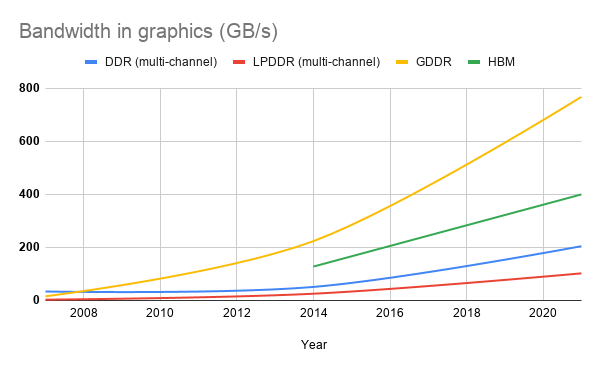
Looking at the graph it seems like the memory vendors aren't hitting Moore's Law any time soon, and if they are, they're fooling me. A similar chart should be made for execution unit counts, but I'm too lazy. A Tigerlake GT2 has 96 Eus. If you go back to our back of the envelope calculation we had a mid range GPU at 24 EUs, so that has quadrupled. In other words, the system architects will use all the bandwidth they can get.
Improving memory technologies is vitally important, it just isn't enough.
TOTAL SAVINGS = 0%
Hardware Composition
One obvious place we want to try to reduce bandwidth is composition. It was after all the biggest individual consumer of available memory bandwidth.
With composition as we described earlier, there was presumed to be a single plane. Software would arrange the various windows onto the plane, which if you recall from the section on composition added quite a bit to the bandwidth consumption, then the display engine could display from that plane.
Hardware composition is the notion that each of those windows could have a separate display plane, directly write into that, and all the compositor would have to do is make sure those display planes occupied the right part of the overall screen. It's conceptually similar to the direct scanout we described earlier in the section on composition.

| Operation | Color Depth | Description | Bandwidth | R/W |
|---|---|---|---|---|
TOTAL SAVINGS = 1.875MB⁄s (33% savings)
Hardware Compsition Verdict
33% savings is really really good, and certainly if you have hardware with this capability, the driver should enable it, but there are some problems that come along with this that make it not so appealing.
- Hardware has a limited number of planes.
- Formats. One thing I left out about the compositor earlier is that one of things it may opt to do is convert the application's window into a format that the display hardware understands. This means some amount of negotiation has to take place so the application knows about this. Prior to this work, that wasn't in place.
- Doesn't reduce any other parts of process, ie. a full screen application wouldn't benefit at all.
Texture Compression
So far in order to solve the, not enough bandwidth, problem, we've tried to add more bandwidth, and reduce usage with hardware composition. The next place to go is to try to tackle texture consumption from texturing.
If you recall, we split the texturing up into two stages. Texture upload, and texture fetch. This third proposed solution attempts to reduce bandwidth by storing a compressed texture in memory. Texture upload will compress it while uploading, and texture sampling can understand the compression scheme and avoid doing all the lookups. Compressing the texture usually comes with some unperceivable degradation. In terms of the sampling, it's a bit handwavy to say you reduce by the compression factor, but let's say for simplicity sake, that's what it does.
Some common formats at the time of the original materials were
| Format | Compression Ratio |
|---|---|
| DXT1 | 8:1 |
| ETC2 | 4:1 |
| ASTC | Variable, 6:1 |
Using DXT1 as an example of the savings:
| Operation | Color Depth | Bandwidth | R/W |
|---|---|---|---|
| Texture Upload | DXT1 | 2KB (64 × 64 × 4 / 8) | W |
| Texel Fetch (nearest) | DXT1 | 2KB (64 × 64 × 4 / 8) | R |
| FB Write | 1Bpc | 16KB (64 × 64 × 4) | W |
| Compositing | 1Bpc | 32KB (64 × 64 × 4 × 2) | R+W |
| Scanout | 1Bpc | 16KB (64 × 64 × 4) | R |
Here's an example with the simple DXT1 format:

Texture Compression Verdict
Texture compression solves a couple of the limitations that hardware composition left. Namely it can work for full screen applications, and if your hardware supports it, there isn't a limit to how many applications can make use of it. Furthermore, it scales a bit better because an application might use many many textures but only have 1 visible window.
There are of course some downsides.

For comparison, here is the same cube scaled down with an 8:1 ratio. As you can see DXT1 does a really good job.

We can't ignore the degradation though as certain rendering may get very distorted as a result.
- Lossy (perhaps).
- Hardware compatibility. Application developers need to be ready and able to compress to different formats and select the right things at runtime based on what the hardware supports. This takes effort both in the authoring, as well as the programming.
- Patents.
- Display doesn't understand this, so you need to decompress before display engine will read from a surface that has this compression.
- Doesn't work well for all filtering types, like anisotropic.
*TOTAL SAVINGS (DXT1) = 1.64MB⁄s (30% savings)
*total savings here is kind of a theoretical max
End to end lossless compression
So what if I told you there was a way to reduce your memory bandwidth consumption without having to modify your application, without being subject to hardware limits on planes, and without having to wait for new memory technologies to arrive?
End to end loss compression attempts to provide both "end to end" and "lossless" compression transparently to software. Explanation coming up.
End to End
As mentioned in the previous section on texture compression, one of the pitfalls is that you'd have to decompress the texture in order for it to be used outside of your 3d engine. Typically this would mean for the display engine to scanout out from, but you could also envision a case where perhaps you'd like to share these surfaces with the hardware video encoder. The nice thing about this "end to end" attribute is every stage we mentioned in previous sections that required bandwidth can get the savings just by running on hardware and drivers that enable this.
Lossless
Now because this is all transparent to the application running, a lossless compression scheme has to be used so that there aren't any unexpected results. While lossless might sound great on the surface (why would you want to lose quality?) it reduces the potential savings because lossless compression algorithms are always more inefficient, but it's still a pretty big win.
What's with the box, bro?
I want to provide an example of how this can be possible. Going back to our original image of the full picture, everything looks sort of the same. The only difference is there is a little display engine decompression step, and all of the sampler and framebuffer write steps now have a little purple box accompanying them

One sort of surprising aspect of this compression is it reduces bandwidth, not overall memory usage (that's also true of the Intel implementation). In order to store the compression information, hardware carves off a little bit of extra memory which is referenced for each operation on a texture (yes, that might use bandwidth too if it's not cached).
Here's a made-up implementation which tracks state in a similar way to Skylake era hardware, but the rest is entirely made up by me. It shows that even a naive implementation can get up to a lossless 2:1 compression ratio. Remember though, this comes at the cost of adding gates to the design and so you'd probably want something better performing than this.

Everything is tracked as cacheline pairs. In this example we have state called "CCS". For every pair of cachelines in the image, 2b are in this state to track the current compression. When the pair of cachelines uses 12 or fewer colors (which is surprisingly often in real life), we're able to compress the data into a single cacheline (state becomes '01'). When the data is compressed, we can reassemble the image losslessly from a single cacheline, this is 2:1 compression because 1 cacheline gets us back 2 cachelines worth of pixel data.
Walking through the example we've been using of the Rubik's cube.
- As the texture is being uploaded, the hardware observes all the runs of the same color and stores them in this compressed manner by building the lookup table. On doing this it modifies the state bits in the CCS to be 01 for those cachelines.
- On texture fetch, the texture sampler checks the CCS. If the encoding is 01, then the hardware knows to use the LUT mechanism instead for all the color values.
- Throughout the rest of rendering, steps 1 & 2 are repeated as needed.
- When display is ready to scanout the next frame, it too can look at the CCS determine if there is compression, and decompress as it's doing the scanout.
The memory consumed is minimal which also means that any bandwidth usage overhead is minimal. In the example we have a 64x128 image. In total that's 512 cachelines. At 2 bits per 2 cachelines the CCS size for the example would be not even be a full cacheline: 512 / 2 / 2 = 128b = 16B
* Unless you really want to understand how hardware might actually work, ignore the 00 encoding for clear color.
* There's a caveat here that we assume texture upload and fetch use the sampler. At the time of the original presentation, this was not usually the case and so until the FB write occurred, you didn't actually get compression.
Theoretical best savings would compress everything:
| Operation | Color Depth | Description | Bandwidth | R/W |
|---|---|---|---|---|
| Texture Upload | 1Bpc compressed | File to DRAM | 8KB (64 × 64 × 4) / 2 | W |
| Texel Fetch (nearest) | 1Bpc compressed | DRAM to Sampler | 8KB (64 × 64 × 4) / 2 | R |
| FB Write | 1Bpc compressed | GPU to DRAM | 8KB (64 × 64 × 4) / 2 | W |
| Compositing | 1Bpc compressed | DRAM to DRAM | 16KB (64 × 64 × 4 × 2) / 2 | R+W |
| Scanout | 1Bpc compressed | DRAM to PHY | 8KB (64 × 64 × 4) / 2 | R |
TOTAL SAVINGS = 2.8125MB⁄s (50% savings)
And if you use HW compositing in addition to this...
TOTAL SAVINGS = 3.75MB⁄s (66% savings)
Ending Notes
Hopefully it's somewhat clear how 3d applications are consuming memory bandwidth, and how quickly the consumption grows when adding more applications, textures, screen size, and refresh rate.
End to end lossless compression isn't always going to be a huge win, but in many cases it can really chip away at the problem enough to be measurable. The challenge as it turns out is actually getting it hooked up in the driver and rest of the graphics software stack. As I said earlier, just because a feature seems good doesn't necessarily mean it would be worth the software effort to implement it. End to end loss compression is one feature that you cannot just turn on by setting a bit, and the fact that it's still not enabled anywhere, to me, is an indication that effort and gates may have been better spent elsewhere.
However, next section will be all about how we got it hooked up through the graphics stack.
If you've made it this far, you probably could use a drink. I know I can.