GEN Graphics and the URB
Table Of Contents
- Introduction
- Vertices
- Intel GPU Hardware and the i965 Driver
- Programming the Hardware
- The URB
- Closing
Introduction
If you were waiting for a new post to learn something new about Intel GEN
graphics, I am sorry. I started moving away from i915 kernel development about
one year ago. Although I had worked landed patches in mesa before, it has
taken me some time to get to a point where I had enough of a grasp on things to
write a blog post of interest. I did start to write a post about the i965
compiler, but I was never able to complete it. ((I spent a significant amount of
time and effort writing about the post about the GLSL compiler in mesa with a
focus on the i965 backend. If you've read my blog posts, hopefully you see that
I try to include real spec reference and code snippets (and pretty pictures). I
started work on that before NIR was fully baked, and before certain people
essentially rewrote the whole freaking driver. Needless to say, by the time I
had a decent post going, everything had changed. Sadly it would have been great
to document that part of the driver, but I discarded that post. If there is any
interest in me posting what I had written/drawn, maybe I'd be willing to post
what I had done in its current state.))
In general I think the documentation has gotten quite good at giving the full details and explanations in a reasonable format. In terms of diagrams and prose, the GEN8+ Programmer Reference Manuals blow the previous docs out of the water. The greatest challenge I see though is the organization of the information which is arguably worse on newer documentation. Also, there is so much of it that it's very difficult to be able to find everything you need when you need it; and it is especially hard when you don't really know what you're looking for. Therefore, I thought it would be valuable to people who want to understand this part of the Intel hardware and the i965 driver. More importantly, I have a terrible memory, and this will serve as good documentation for future me.
I try very hard to strike a balance between factual accuracy and in making the information consumable. If you feel that either something is grossly inaccurate, or far too confusing, please let me know.
[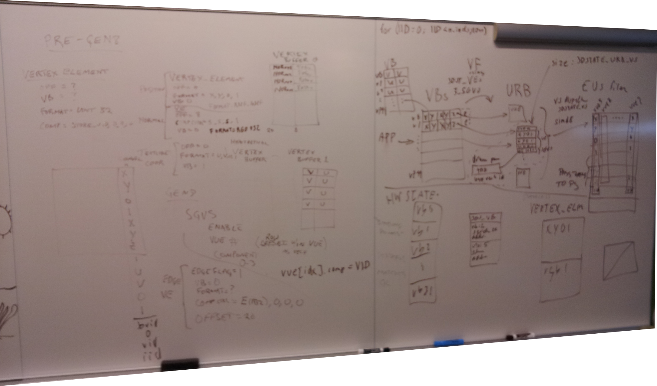 Blurry picture of the resulting whiteboard
Vertices
One of the most important components that goes into a building a 3d scene is a vertex. The point represented by the vertex may simply be a point or it may be part of some amalgamation of other points to make a line, shape, mesh, etc. Depending on the situation, you might observe a set of vertices referred to as: topology, primitive, or geometry (these aren't all the same thing, but unless you're speaking to a pedant you can expect the terms to be interchanged pretty frequently). Most often, these vertices are parts of triangles which make up a more complex model which is part of a scene.
The first stage in modern current programmable graphics pipeline is the
Vertex Shader which unsurprisingly operates on the vertices. (I find the
word "pipeline" a bit misleading here, but maybe that's just me. It's not
specific enough. It seems to imply that a vertex is the smallest atom for which
the GPU will operate on, and while that's true, it ignores the massively
parallel nature of the beast. There are other oddities as well, like streamout)
In the simplest case you might use a vertex shader to simply locate the vertex
in the correct place using the model, and view transformations. Don't worry if
you're asking yourself why is it called a shader. Given the example there isn't
anything I would define as "shading" either. How clever programmers make use of
the vertex shader is out of scope, thankfully - but rest assured it's not always
so simple.

Vertex Buffers
The attributes that define a vertex are called, Vertex Attributes (yay). For now you can just imagine the most obvious attribute - position. The attributes are stored in one or more buffers that are created and defined by the Graphics API. Each vertex (defined here as a collection of all the attributes for a single point) gets processed and/or modified by the vertex shader with the program that is also specified by the API.
It is the responsibility of the application to build up the vertex buffers. I already mentioned that position is a very common attribute describing a vertex; unless you're going to be creating parts of your scene within a shader, it's likely a required attribute. So the programmer in one way or another will define each position of every vertex for the scene. We can have other things though, and the purpose of the current programmable GPU pipelines is to allow the sky to be the limit. Colors and normals are some other common vertex attributes. With a few more magic API calls, we'll have a nice 2d image on the screen that represents the 3D image provided via the vertices.
Here are some links with much more detailed information:
Intel GPU Hardware and the i965 Driver
The GPU hardware will need to be able to operate on the vertices that are contained in the buffers created by the programmer. It will also need to be able to execute a shader program specified by the programmer. Setting this up is the responsibility of the GPU driver. When I say driver, I mean like the i965 driver in mesa. This is just a plain old shared object sitting on your disk. This is not some kernel component. In graphics, the kernel driver knows less about the underlying 3d hardware than the userspace driver.
Ultimately, the driver needs to take all the API goop and make sure it programs the hardware correctly for the given goop. There will be details on this later in the post. Getting the shader program to run takes some amount of state setup, relatively little. It's primarily a different component within the driver which implements this. Modern graphics drivers have a surprisingly full featured compiler within them for being able to convert the API's shading language into the native code on the GPU.
Execution Units
Programmable shading for all stages in the GPU pipeline occurs on Execution Units which are often abbreviated to EU. All other stuff is generally called, "fixed function". The Execution Units are VLIW processors. The ISA for the EU is documented. The most important point I need to make is that each thread of each EU has its own register file. If you're unfamiliar with the term register file, you can think of it as thread local memory. If you're unfamiliar with that, I'm sorry.
Push vs. Pull Vertex Attributes
As it pertains to the shader, Vertex Attributes can be pushed, or pulled [or both]. Intel and most other hardware started with the push model. This is because there was no programmable shaders for geometry in the olden days. Some of the hardware vendors have moved exclusively from push to pull. Since Intel hardware can do both (as is likely the case for any HW supporting the push model), I'll give a quick overview mostly as a background. The Intel docs do have a comparison of the two which I noticed after writing this section. I am too lazy to find the link :P
In the pull model, none of the vertex attributes needed by the shader program are fetched before execution of the shader program beings. Assuming you can get the shader programs up and running quickly, and have a way to hide the memory latency (like relatively fast thread switching). This comes with some advantages (maybe more which I haven't thought of):
- In programs with control flow or conditional execution, you may not need all the attributes.
- Fewer transistors for fixed function logic.
- Assuming the push model requires register space - more ability to avoid spills
when there are a lot of vertex attributes.
- More initial register space for the programs
- The push model has fixed function hardware that is designed to fetch all the vertex attributes and populate it into the shader program during invocation. Unlike the pull model, all attributes that may be needed are fetched and this can cause some overhead.
- It doesn't suffer from the two requirements above though (fast shader invocation + latency hiding).
- Can do format conversion automatically.
- Hardware should also have a better view of the system and be able to more intelligently do the attribute pushing, perhaps utilizing caches better, or considering memory arbiters better, etc.
As already mentioned, usually if your hardware supports the push model, you can optionally pull things as needed, and you can easily envision how these things may work. That is especially useful on GEN in certain cases where we have hardware constraints that make the push model difficult, or even impossible to use.

Green Square
Before moving on, I'd like to demonstrate a real example with code. We'll use
this to see how the attributes make their way down the pipeline. The shader
program will simply draw a green square. Such a square can be achieved very
easily without a vertex shader, or more specifically, without passing the color
through the vertex shader, but this will circumvent what I want to demonstrate.
I'll be using shader_runner from the piglit GL test suite and framework. The
i965 driver has several debug capabilities built into the driver and exposed via
environment variables. In order to see the contents of the commands emitted by
the driver to the hardware in a
batchbuffer,
you can set the environment variable INTEL_DEBUG=batch. The contents of the
batchbuffers will be passed to libdrm for decoding ((The decoding within libdrm
is quite old and crufty. Most, if not everything in this post was hand decoded
via the specifications for the commands in the public
documentation).
The shader programs get disassembled to the native code by the i965 driver (To
dump the generated vertex shader and fragment shader in native code (with some
amount of the IR), you similarly add fs, and vs. To dump all three things at
once for example: INTEL_DEBUG=batch,vs,fs).
Here is the linked shader we'll be using for shader_runner:
[require]
GLSL >= 1.30

[vertex shader]
varying vec4 color;
void main()
{
  color = vec4(0,1,0,1);
  gl_Position = gl_Vertex;
}

[fragment shader]
varying vec4 color;

void main()
{
  gl_FragColor = color;
}

[test]
draw rect -1 -1 2 2
From the shader program we can infer the vertex shader is reading from exactly
one input variable: gl_Vertex and is going to "output" two things: the
varying vec4 color, and the built-in vec4 gl_Position. Here is the
disassembled program from invoking INTEL_DEBUG=vs Don't worry if you can't
make sense of the assembly that follows. I'm only trying to show the reader that
the above shader program is indeed fetching vertex attributes with the
aforementioned push model.
mov(8)          g119<1>UD       g1<8,8,1>UD                     { align1 WE_all 1Q compacted };
mov(8)          g120<1>F        g2<8,8,1>F                      { align1 1Q compacted };
mov(8)          g121<1>F        g3<8,8,1>F                      { align1 1Q compacted };
mov(8)          g122<1>F        g4<8,8,1>F                      { align1 1Q compacted };
mov(8)          g123<1>F        g5<8,8,1>F                      { align1 1Q compacted };
mov(8)          g124<1>F        [0F, 0F, 0F, 0F]VF              { align1 1Q compacted };
mov(8)          g125<1>F        1F                              { align1 1Q };
mov(8)          g126<1>F        [0F, 0F, 0F, 0F]VF              { align1 1Q compacted };
mov(8)          g127<1>F        1F                              { align1 1Q };
send(8)         null            g119<8,8,1>F
                            urb 1 SIMD8 write mlen 9 rlen 0                 { align1 1Q EOT };
Ignore that first mov for now. That last send instruction indicates that
the program is outputting 98 registers of data as determined by mlen.
Yes, mlen is 9 because of that first mov I asked you to ignore. The rest of the
information for the send instruction won't yet make sense. Refer to Intel's
public documentation if you want to know more about the send
instruction,
but hopefully I'll cover most of the important parts by the end. The constant
0,1,0,1 ((The layout is RGBA, ie. completely opaque green value.
https://en.wikipedia.org/wiki/RGBA_color_space)) values which are moved to
g124-g127 should make it clear what color corresponds to, which means the
other thing in g120-g123 is gl_Position, and g2-g5 is gl_Vertex (because
gl_Position = gl_Vertex;).

- Either you already know how this stuff works, or that should seem weird. We have two vec4 things, color and position, and yet we're passing 8 vec4 registers down to the next stage - what are the other 6? Well that is the result of SIMD8 dispatch.
Programming the Hardware
Okay, fine. Vertices are important. The various graphics APIs all give ways to specify them, but unless you want to use a software renderer, the hardware needs to be made aware of them too. I guess (and I really am guessing) that most of the graphics APIs are similar enough that a single set of HW commands are sufficient to achieve the goal. It's actually not a whole lot of commands to do this, and in fact they make a good deal of sense once you understand enough about the APIs and HW.
For the very simple case, we can reduce the number of commands needed to get vertices into the GPU pipeline to 3. There are certainly other very important parts of setting up state so things will run correctly, and the not so simple cases have more commands just for this part of the pipeline setup.
- Here are my vertex buffers - 3DSTATE_VERTEX_BUFFERS
- Here is how my vertex buffers are laid out - 3DSTATE_VERTEX_ELEMENTS
- Do it - 3DPRIMITIVE
There is a 4th command which deserves honorable mention, 3DSTATE_VS. We're going to have to defer dissecting that for now.
The hardware unit responsible for fetching vertices is simply called the Vertex Fetcher (VF). It's the fixed function hardware that was mentioned earlier in the section about push vs pull models. The Vertex Fetcher's job is to feed the vertex shader, and this can be split into two main functional objectives, transferring the data from the vertex buffer into a format which can be read by the vertex shader, and allocating a handle and special internal memory for the data (more later).
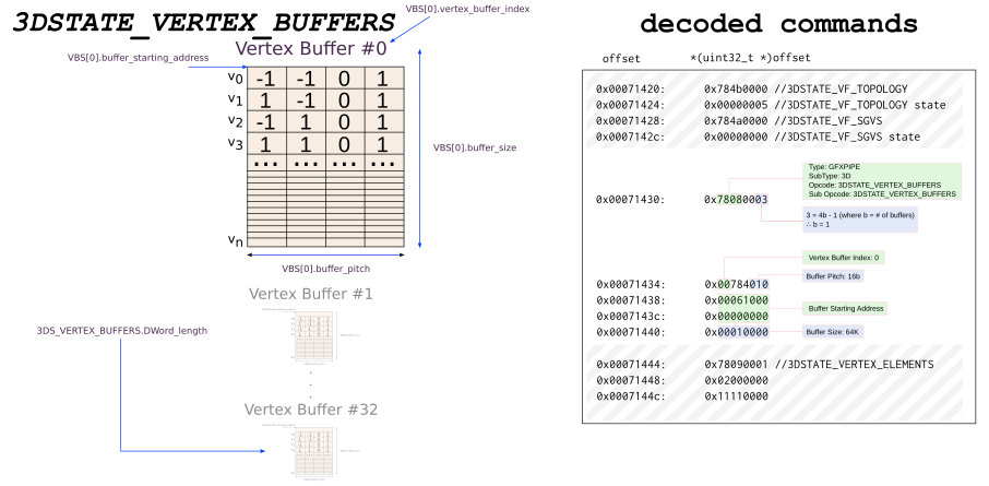
3DSTATE_VERTEX_BUFFERS
The API specifies a vertex buffer which contains very important things for rendering the scene. This is done with a command that describes properties of the vertex buffer. From the 3DSTATE_VERTEX_BUFFERS documentation:
This structure is used in 3DSTATE_VERTEX_BUFFERS to set the state associated with a VB. The VF function will use this state to determine how/where to extract vertex element data for all vertex elements associated with the VB.
(the actual inline data is defined here: VERTEX_BUFFER_STATE)
In my words, the command specifies a number of buffers in any order which are "bound" during the time of drawing. These binding points are needed by the hardware later when it actually begins to fetch the data for drawing the scene. That is why you may have noticed that a lot of information is actually missing from the command. Here is a diagram which shows what a vertex buffer might look like in memory. This diagram is based upon the green square vertex shader described earlier.
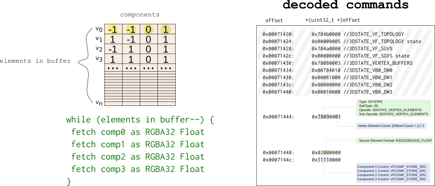
3DSTATE_VERTEX_ELEMENTS
The API also specifies the layout of the vertex buffers. This entails where the actual components are as well as the format of the components. Application programmers can and do use lots of cooky stuff to do amazing things, which is again, thankfully out of scope. As an example, let's suppose our vertices are comprised of three attributes, a 2D coordinate X,Y; a Normal vector U, V; and a color R, G, B.

In the above picture, the first two have very similar programming. They have the same number of VERTEX_ELEMENTS. The third case is a bit weird even from the API perspective, so just consider the fact that it exists and move on.
Just like the vertex buffer state we initialized in hardware, here too we must initialize the vertex element state.
SVG Image for vertext buffer/element diagrams
I don't think I've posted driver code yet, so here is some. What the code does is loop over every enabled attribute enum gl_vert_attrib (GL defines some and some are generic) and is setting up the command for transferring the data from the vertex buffer to the special memory we'll talk about later. The hardware will have a similar looking loop (the green text in the above diagram) to read these things and to act upon them.
BEGIN_BATCH(1 + nr_elements * 2);
OUT_BATCH((_3DSTATE_VERTEX_ELEMENTS << 16) | (2 * nr_elements - 1));
for (unsigned i = 0; i < brw->vb.nr_enabled; i++) {
   struct brw_vertex_element *input = brw->vb.enabled[i];
   uint32_t format = brw_get_vertex_surface_type(brw, input->glarray);
   uint32_t comp0 = BRW_VE1_COMPONENT_STORE_SRC;
   uint32_t comp1 = BRW_VE1_COMPONENT_STORE_SRC;
   uint32_t comp2 = BRW_VE1_COMPONENT_STORE_SRC;
   uint32_t comp3 = BRW_VE1_COMPONENT_STORE_SRC;

   switch (input->glarray->Size) {
   case 0: comp0 = BRW_VE1_COMPONENT_STORE_0;
   case 1: comp1 = BRW_VE1_COMPONENT_STORE_0;
   case 2: comp2 = BRW_VE1_COMPONENT_STORE_0;
   case 3: comp3 = input->glarray->Integer ? BRW_VE1_COMPONENT_STORE_1_INT
                                           : BRW_VE1_COMPONENT_STORE_1_FLT;
      break;
   }

   OUT_BATCH((input->buffer << GEN6_VE0_INDEX_SHIFT) |
             GEN6_VE0_VALID |
             (format << BRW_VE0_FORMAT_SHIFT) |
             (input->offset << BRW_VE0_SRC_OFFSET_SHIFT));

   OUT_BATCH((comp0 << BRW_VE1_COMPONENT_0_SHIFT) |
             (comp1 << BRW_VE1_COMPONENT_1_SHIFT) |
             (comp2 << BRW_VE1_COMPONENT_2_SHIFT) |
             (comp3 << BRW_VE1_COMPONENT_3_SHIFT));
}
3DPRIMITIVE
Once everything is set up, 3DPRIMITIVE tells the hardware to start doing stuff. Again, much of it is driven by the graphics API in use. I don't think it's worth going into too much detail on this one, but feel free to ask questions in the comments...
The URB
Modern GEN hardware has a dedicated GPU memory which is referred to as L3 cache. I'm not sure there was a more confusing way to name it. I'll try to make sure I call it GPU L3 which separates it from whatever else may be called L3. ((Originally, and in older public docs it is sometimes referred to as Mid Level Cache (MLC), and I believe they are exactly the same thing. MLC was the level before Last Level Cache (LLC), which made sense, until Baytrail which had a GPU L3, but did not have an LLC.)) The GPU L3 is partitioned into several functional parts, the largest of which is the special URB memory.
The Unified Return Buffer (URB) is a general purpose buffer used for sending data between different threads, and, in some cases, between threads and fixed function units (or vice versa).
...
The Thread Dispatcher (TD) is the main source of URB reads. As a part of spawning a thread, pipeline fixed functions provide the TD with a number of URB handles, read offsets, and lengths. The TD reads the specified data from the URB and provide that data in the thread payload pre loaded into GRF registers.
I'll explain that quote in finer detail in the next section. For now, simply recall from the first diagram that we have some input which goes into some geometry part of the pipeline (starting with vertex shading), followed by rasterization (and other fixed function things), followed by fragment shading. The URB is what is containing the data of this geometry as it makes its way through the various stages within that geometry part of this pipeline. The fixed function part of the hardware will consume the data from the URB at which point it can be reused for the next set of geometry.
To summarize, the data going through the pipeline may exist in 3 types of memory depending on the stage and the hardware:
- Graphics memory (GDDR on discrete cards, or system memory on integrated graphics).
- The URB.
- The Execution Unit's register file
URB space must be divided among the geometry shading stages. To do this, we have state commands like 3DSTATE_URB_VS. Allocation granularity is in 512b chunks which one might make an educated guess is based on the cacheline size in the system (cacheline granularity tends to be the norm for internal clients of memory arbiters can request).
Boiling down the URB allocation in mesa for the VS, you get an admittedly difficult to understand thing.
unsigned vs_size = MAX2(brw->vs.prog_data->base.urb_entry_size, 1);
unsigned vs_entry_size_bytes = vs_size * 64;
...
unsigned vs_wants =
   ALIGN(brw->urb.max_vs_entries * vs_entry_size_bytes,
         chunk_size_bytes) / chunk_size_bytes - vs_chunks;
The vs_entry_size_bytes is the size of every "packet" which is delivered to
the VS shader thread with the push model of execution (keep this in mind for the
next section).
count = _mesa_bitcount_64(vs_prog_data->inputs_read);
unsigned vue_entries =
   MAX2(count, vs_prog_data->base.vue_map.num_slots);

vs_prog_data->base.urb_entry_size = ALIGN(vue_entries, 4) / 4;
Above, count is the number of inputs for the vertex shader, and let's defer a bit on num_slots. Ultimately, we get a count of VUE entries.
WTF is a VUE
The Vertex Fetcher and the Thread Dispatcher will work in tandem to get a Vertex Shader thread running with all the correct data in place. A VUE handle is created for some portion of the URB with the specified size at the time the Vertex Fetcher acts upon a 3DSTATE_VERTEX_ELEMENT. The Vertex Fetcher will populate some part of the VUE based on the contents of the vertex buffer as well as things like adding the handle it generated, and format conversion. That data is referred to as the VS thread payload, and the functionality is referred to as Input Assembly (The documentation there is really good, you should read that page). It's probably been too long without a picture. The following picture deviates from our green square example in case you are keeping a close eye.
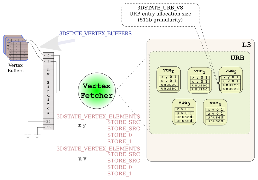 VF create VUEs
There are a few things you should notice there. The VF can only write a full vec4 into the URB. In the example there are 2 vec2s (a position, and a normal), but the VF must populate the remaining 2 elements. We briefly saw some of the VERTEX_ELEMENT fields earlier but I didn't explain them. The STORE_SRC instructs the VF to copy, or convert the source data from the vertex buffer and write it into the VUE. STORE_0 and STORE_1 do not read from the vertex buffer but they do write in a 0, and 1 respectively into the VUE. The terminology that seems to be the most prevalent for the vec4 of data in the VUE is "row". ie. We've used 2 rows per VUE for input, row 0 is the position, row 1 is the normal. The images depict a VUE as an array of vec4 rows.
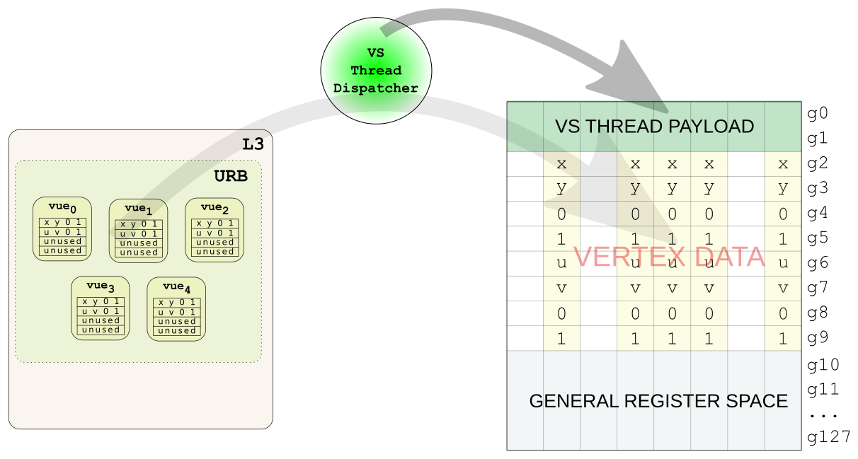 SIMD8 VS Thread Dispatch
A VUE is allocated per vertex, and one handle is allocated for each as well. That happens once (it's more complicated with HS, DS, and GS, but I don't claim to understand that, so I'll skip it for now). That means that as the vertex attributes are getting mutated along the GPU pipeline the output is going to have to be written back into the same VUE space that the input came from. The other constraint is we need to actually setup the VUEs so they can be used by the fixed function pipeline later. This may be deferred until a later stage if we're using other geometry shading stages, or perhaps ignored entirely for streamout. To sum up there are two requirements we have to meet:
- The possibly modified vertex data for a given VUE must be written back to the same VUE.
- We must build the VUE header, also in place of the old VUE. (You could get clever, or buggy, depending on which way you look at it and actually write into a different VUE. The ability is there, but it's not often [if ever] used)
#2 seems pretty straight forward once we find the definition of a VUE header. That should also clear up why we had a function doing MAX2 to determine the VUE size in the previous chapter - we need the max of [the inputs, and outputs with a VUE header]. You don't have to bother looking at VUE header definition if you don't want, for our example we just need to know that we need to put an X, Y, Z, W in DWord 4-7 of the header. But how are we going to get the data back into the VUE... And now finally we can explain that 9th register (and mov) I asked you to ignore earlier. Give yourself a pat on the back if you still remember that.
Well we didn't allocate the handles or the space in the URB for the VUEs. The Vertex Fetcher hardware did that. So we can't possibly know where they are. But wait! VS Thread Payload for SIMD8 dispatch does have some interesting things in it. Here's my simplified version of the payload from the table in the docs: [table id=2 /]
Oh. g1 contains the "return" handles for the VUEs. In other words, the thing to reference the location of the output. Let's go back to the original VS example now
mov(8)          g119<1>UD       g1<8,8,1>UD                     { align1 WE_all 1Q compacted };
mov(8)          g120<1>F        g2<8,8,1>F                      { align1 1Q compacted };
mov(8)          g121<1>F        g3<8,8,1>F                      { align1 1Q compacted };
mov(8)          g122<1>F        g4<8,8,1>F                      { align1 1Q compacted };
mov(8)          g123<1>F        g5<8,8,1>F                      { align1 1Q compacted };
mov(8)          g124<1>F        [0F, 0F, 0F, 0F]VF              { align1 1Q compacted };
mov(8)          g125<1>F        1F                              { align1 1Q };
mov(8)          g126<1>F        [0F, 0F, 0F, 0F]VF              { align1 1Q compacted };
mov(8)          g127<1>F        1F                              { align1 1Q };
send(8)         null            g119<8,8,1>F
                            urb 1 SIMD8 write mlen 9 rlen 0                 { align1 1Q EOT };
With what we now know, we should be able to figure out what this means. Recall that we had 4 vertices in the green square. The destination of the mov instruction is the first register, so our chunk of data to be sent in the URB write message is:
    g119 <= URB return handles
    g120 <= X X X X ? ? ? ?
    g121 <= Y Y Y Y ? ? ? ?
    g122 <= Z Z Z Z ? ? ? ?
    g123 <= W W W W ? ? ? ?
    g124 <= 0 0 0 0 0 0 0 0
    g125 <= 1 1 1 1 1 1 1 1
    g126 <= 0 0 0 0 0 0 0 0
    g127 <= 1 1 1 1 1 1 1 1
The send command [message], like the rest of the ISA operates upon a channel.
In other words, read the values in column order. Send outputs n (9 in this case)
registers worth of data. The URB write is pretty straightforward, it just writes
n-1 (8 in this case) elements from the channel consuming the first register as
the URB handle. That happens across all 8 columns because we're using SIMD8
dispatch. URB return handle, x, y, z, w, 0, 1, 0, 1. So that's good, but if
you are paying very close attention, you are missing one critical detail, and
not enough information is provided above to figure it out. I'll give you a
moment to go back in case I got your curiosity......
As we already stated above, DWord 4-7 of the VUE header has to be XYZW. So if you believe what I told you about URB writes, what we have above is going to end up with XYZW in DWORD 0-3, and RGBA in DWord4-7. That means the position will be totally screwed, and the color won't even get passed down to the next stage (because it will be VUE header data). This is solved with the global offset field in the URB write message. To be honest, I don't quite understand how the code implements this (it's definitely in src/mesa/drivers/dri/i965/brw_fs_visitor.cpp). I can go find the references to the URB write messages, and dig around the i965 code to figure out how it works, or you can do that and I'll do one last diagram. What; diagram? Good choice.
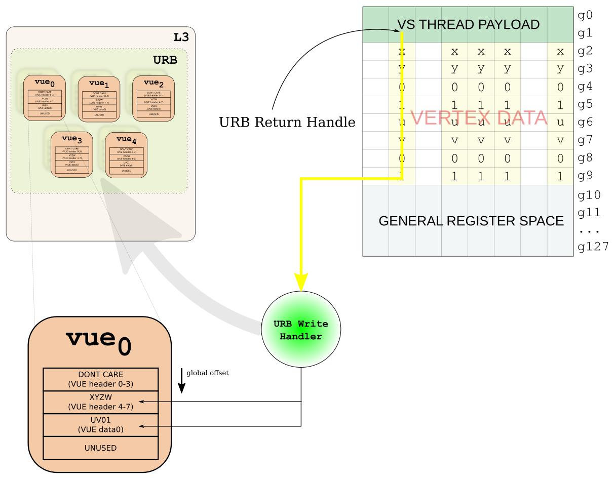 URB writeback from VS
Closing
For me, writing blog posts like this is like writing a big patch series. You write and correct so many times that you become blind to any errors. Wordpress says I am closing in on my 300th revision (and that of course excludes the diagrams). Please do let me know if you notice any errors.
I really wanted to talk about a few other things actually. The way SGVs work for VertexID, InstanceID, and the edge flag. Unfortunately, I think I've reached the limit on information that should be in a single blog post. Maybe I'll do those later or something. Here is the gradient square using VertexID which I was planning to elaborate upon (that is why the first picture had a gradient square):
[require]
GLSL >= 1.30

[vertex shader]
varying vec4 color;
void main()
{
  color = vec4(gl_VertexID == 0, gl_VertexID == 1,
        gl_VertexID == 2, 1);
  gl_Position = gl_Vertex;
}

[fragment shader]
varying vec4 color;

void main()
{
  gl_FragColor = color;
}

[test]
draw rect -1 -1 2 2